
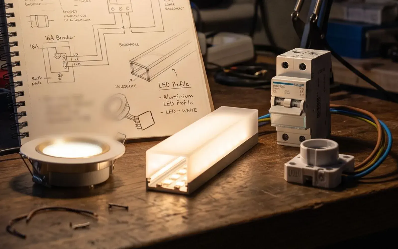
How the Electrica calculator works
What stands behind every figure the calculator gives: illuminance targets, the room's factors, the grid and the colour of light, the power supply and cable for a strip, cable trays, the socket and switch points.
How much light: illuminance targets
The “Room illuminance” calculator starts not with a fitting but with a question: how much light does this room need. Illuminance is measured in lux (lx) — the luminous flux, in lumens, that falls on one square metre.
For living spaces the calculator uses the IES recommended levels; for workplaces, the European standard EN 12464-1. The first figure is general light, the second the task zone: • living room — 200 / 400 lx • bedroom — 100 / 300 lx • kitchen — 300 / 500 lx • bathroom — 200 / 400 lx • home office — 400 / 500 lx • dining room — 150 / 300 lx • hallway — 75 / 150 lx • production workshop — 300 / 500 lx • warehouse — 100 / 200 lx • shop, sales floor — 300 / 500 lx
General light lights the whole room. A task zone — a worktop, a desk, a bench — needs more, and it is made up with local light: a light over the worktop, a desk lamp, a fitting over the bench. That is why the calculator works out the general light and shows the task figure separately.
If you know your own target — say a designer has set 500 lx for a whole office — you can enter it by hand instead of the table's.
How many fittings: the lumen method
The calculator counts fittings by the lumen method — the same one designers use in DIALux:
N = E × A ÷ (Φ × UF × MF)
E is the illuminance you need in lux, A the area in m², Φ the luminous flux of one fitting in lumens (it is on the product card), UF the utilisation factor, MF the maintenance factor.
The utilisation factor (UF) says what share of a fitting's light reaches the work plane. It depends on the room's shape — its index:
k = L × W ÷ (hm × (L + W))
L and W are the length and width, hm the height of the fitting above the work plane: the ceiling height minus 0.85 m (the height of a desk or worktop), or the whole ceiling height in a hallway or warehouse, where the work happens at floor level. A wide, low room gives the work plane more light; a tall, narrow one gives it less. The finishes matter too: a white ceiling reflects about 70% of the light, pale walls 50%, grey 30%, dark 10%.
The maintenance factor (MF) allows for fittings gathering dust and LEDs losing brightness over time: 0.85 for a clean flat, 0.8 for a kitchen or bathroom, 0.7 for a workshop or warehouse.
Example: a living room 5 × 4 m, ceiling 2.7 m, white ceiling and pale walls, an 800 lm fitting. • hm = 2.7 − 0.85 = 1.85 m • k = 20 ÷ (1.85 × 9) ≈ 1.2 • UF ≈ 0.79, MF = 0.85 • N = 200 × 20 ÷ (800 × 0.79 × 0.85) ≈ 7.5 — so at least 8 fittings
The same fitting in a narrow, tall hallway 8 × 1.6 m with a 3.5 m ceiling works at UF ≈ 0.43 — almost half as well: in a shape like that most of the light goes onto the walls.
The grid, the spacing and the colour of light
The formula gives a minimum, but the fittings still have to be placed. The calculator lays them out on an even grid — the same number in every row — and so it may suggest slightly more than the minimum. In our living room, 7.5 becomes a 4 × 2 grid of 8 fittings, 1.25 m and 2 m apart.
Then it checks the spacing: the distance between neighbouring fittings should not exceed 1.5 times their height above the work plane. For the living room that is 1.5 × 1.85 ≈ 2.8 m, and the grid passes. If the spacing is wider, dark bands appear between the fittings even when there are enough lux in total, and the calculator suggests a denser grid.
The colour of light is advised separately for day and evening: • living room — 4000 K by day, 2700 K in the evening • bedroom — 3500 / 2700 K • kitchen and bathroom — 4000 / 3000 K • home office — 5000 / 4000 K • dining room and hallway — 3000 / 2700 K • workshop — 5000 / 4000 K, warehouse — 4000 K • shop — 4000 / 3000 K The fewer the kelvins, the warmer and calmer the light; cool light keeps people alert and renders colours truer at a workplace. In a shop it is the other way round: warm light makes the goods more appealing.
For the result the calculator picks fittings that are in stock and recounts the quantity for each model by its own flux — which is why different models need different numbers: a 1200 lm fitting needs fewer than a 600 lm one. For a bathroom it shows only models rated IP44 or higher.
A separate tool, “Beam spot diameter”, answers the question for a single fitting: what spot does it give. The spot diameter is D = 2 × h × tan(α/2), where h is the distance to the surface and α the beam angle from the datasheet. A 500 lm spot with a 36° beam at 2.5 m gives a spot about 1.6 m across, with about 240 lx on average inside it.
If the fitting's beam is given as a range — an adjustable spot with a 36–60° lens, say — enter both ends, “from” and “to”. The calculator shows the spot and the light for the narrow and the wide angle: the same spot gives 1.6 to 2.9 m across and from 240 down to about 75 lx. The wider the beam, the bigger the spot and the less light on each point of it. Distances can be entered in metres, centimetres or millimetres, whichever is handier.
LED strip: the power supply and the cable
Three of the calculator's tools solve one problem — making an LED strip light evenly along its whole length.
“Power supply sizing”. A strip's load is its watts per metre times its length. A 25% reserve is added so the supply does not run at its limit and overheat, and the next standard rating up is taken: 15, 30, 36, 60, 75, 100, 150, 200 W and so on up to 600 W. Example: a 14.4 W/m strip, 5 m long, is 72 W; with the reserve, 90 W — so a 100 W supply.
From one end a strip is fed no longer than: 5 V — 2 m, 12 V — 5 m, 24 V — 10 m, 48 V — 20 m. The copper inside the strip is thin, and past that length the far end visibly dims, so the feed goes in at both ends. At 12 V the current is twice what it is at 24 V for the same power: the same 72 W is 6 A at 12 V and 3 A at 24 V.
“Voltage drop”. On the way from the supply to the strip part of the voltage is lost in the wire: ΔU = 2 × L × I × ρ ÷ S, where L is the cable length one way, I the current, ρ = 0.0175 the resistivity of copper and S the cross-section in mm². For a strip no more than 5% is acceptable, or the difference in brightness shows. Example: 24 V, 3 A, a 10 m cable. At 0.75 mm², 1.4 V is lost (5.8%) — too much; at 1.5 mm², 0.7 V (2.9%) — fine.
“Cable cross-section” works the same formula the other way round: from the loss you allow (3% by default) it finds the section needed and rounds it up to one that is actually made: 0.5, 0.75, 1, 1.5, 2.5, 4, 6 mm² and up. Then it checks the heat: each section carries its own current (1.5 mm² — 17.5 A, 2.5 mm² — 24 A), and the larger of the two wins. The same example needs 1.46 mm², so a 1.5 mm² cable.
Sockets and switches: points, frames, mechanisms
The “Sockets and switches” calculator goes room by room: you say which rooms there are and how many, then answer a few questions about each. The answers add up to a list of points.
A point is one place on the wall and one frame. A frame can hold several mechanisms: a switch, a socket, a TV or network outlet, a dimmer. If a socket is wanted where there is already a switch, the calculator does not add a new point — it puts a second mechanism into the same frame, which makes it a 2-gang frame.
Lighting groups. The light in a room can be split into several groups — half the ceiling on one key, half on another, say. Two groups can be done two ways: two separate switches in a 2-gang frame, or one double-key switch in a 1-gang frame. They are different products, so the calculator asks rather than decides for you. A two-way switch controls the light from two places — the door and the bed, or the two ends of a hallway.
Dedicated sockets are for appliances that run for a long time or draw a lot of power: the fridge (preferably earthed), the dishwasher and the washing machine, the cooker hood, the water heater, the air conditioner. Over a kitchen worktop a point is usually a double socket, for two appliances.
At the end the calculator shows every point — what is in it and what it is for — the totals by frame and by mechanism, offers a model series and a colour, and puts the exact list of products into the cart. The list can be downloaded as a PDF.
If the flat's plan is already drawn, the “Mark up your own plan” tool lets you place fittings, sockets and switches straight onto your AutoCAD drawing or a photo of the sheet. The scale is set from one wall of known length, and the drawing is never uploaded — it stays in your browser.
Cable tray: the size and the parts of a route
The “Trays and parts” calculator answers two questions: which tray these cables need, and what else to buy to lay the route. It works on the Electrica quick-mount tray system (LP): 3 m straight sections, a 50 or 100 mm side, widths from 50 to 600 mm.
Size. First the cross-sections of all the cables are added up — the area of a circle by the outer diameter, π × d² ÷ 4, for each cable. The calculator knows the diameters of the usual cables: NYM-type 3×2.5 about 10.5 mm, UTP cat.5e 5.5 mm, RG-6 7 mm; for your own cable take the diameter from its datasheet.
A tray must not be packed to the top: cables warm up, and room is needed for the ones added later. So the tray's section has to exceed the cables' total with a margin — the cables take no more than 40% of it (the fill factor). Section needed = cables' section ÷ 0.4. The calculator takes the smallest tray that holds that; on a tie, the one with the 50 mm side, because every fitting is made for it. The side must also be no lower than the thickest cable.
Example: 12 NYM-type 3×2.5 cables and 6 UTP cables. • cables' section: 12 × 86.6 + 6 × 23.8 ≈ 1,182 mm² • tray section needed: 1,182 ÷ 0.4 ≈ 2,955 mm² • a 50 × 50 tray (2,500 mm²) is too small, 100 × 50 (5,000 mm²) fits — filled to about 24%
The route. Straight sections are the route length ÷ 3 m, rounded up: the missing piece is cut from a whole section. Each bend, tee or cross is a part of its own. A route is one continuous run, so it has one joint fewer than it has parts, and every joint takes two connectors, one on each side wall. Supports go every 1.5 m, plus one at the end and one at every fitting — that is where a run is weakest. A cover, if wanted, is one per section.
Continuing the example: a 30 m route along a wall, four 90° bends and one tee, with a cover. • sections: 30 ÷ 3 = 10, and 10 covers • parts in all: 10 sections + 5 fittings = 15, so 14 joints and 28 connectors • supports: 30 ÷ 1.5 = 20, plus 1 at the end, plus 5 at the fittings = 26
Under the result the calculator shows the real Electrica parts of that size — tray, cover, connector, bends, tees, brackets — with prices and quantities, and one button puts the whole route in the cart. A specialist can change the fill factor (20 to 60%) and the support step (0.5 to 3 m) to suit the project.
Other courses
Lighting basics
How to choose a luminaire by its light rather than its wattage: brightness, colour of light, protection from dust and water.
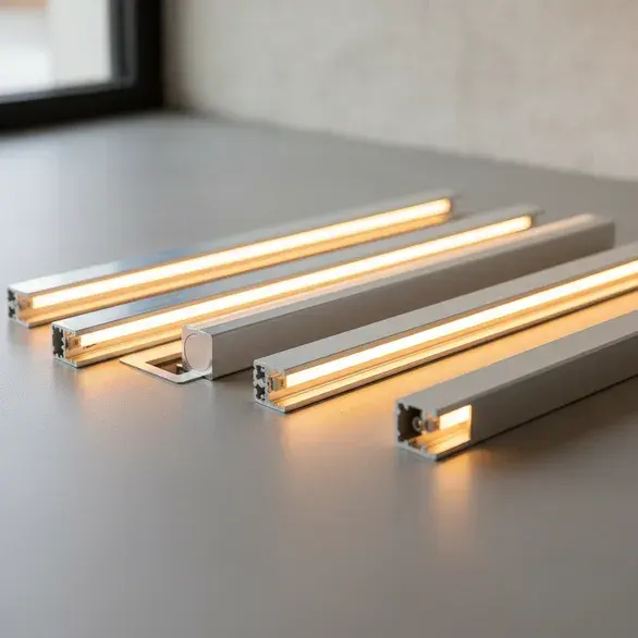
Types of LED luminaires
Recessed, surface, pendant, track, strips and outdoor floodlights — what goes where.
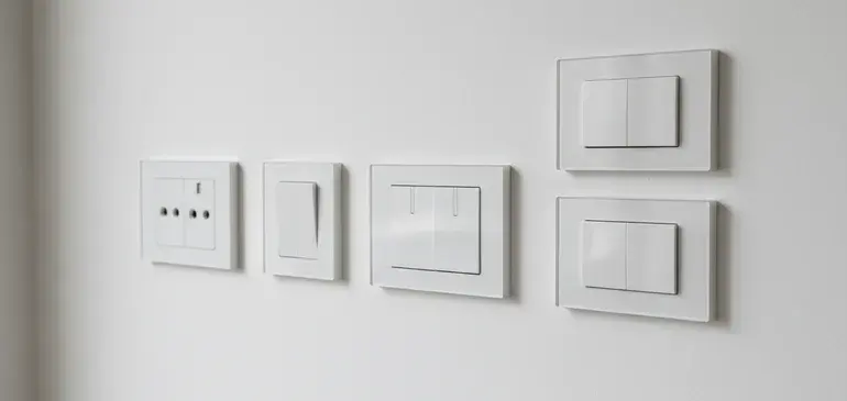
Sockets and switches
Ratings, earthing, two-way switches and dimmers, protection in wet zones.